Beranda
› Draw The Flow Net By Using Nf 3 / 24 Simple Mac Diagram For You | Flow app, Free graphic ... - Nevertheless, the method for drawing a flow net by hand is given in section 2.13 for readers interested in learning the techniques involved.
Selasa, 29 Juni 2021
Draw The Flow Net By Using Nf 3 / 24 Simple Mac Diagram For You | Flow app, Free graphic ... - Nevertheless, the method for drawing a flow net by hand is given in section 2.13 for readers interested in learning the techniques involved.
Draw The Flow Net By Using Nf 3 / 24 Simple Mac Diagram For You | Flow app, Free graphic ... - Nevertheless, the method for drawing a flow net by hand is given in section 2.13 for readers interested in learning the techniques involved.. By inspection of the three forms o f the flow net in figure 4.6 we see that. Draw a trial flow line and then draw in other flow lines to define all the flow tubes; A typical well drawn flow net is illustrated in fig. If one attempts to draw the equipotential lines to complete the flow systems on the diagrams of figure 5.5, it will. We've got three fluorines, though.
Where, nf number of flow channels ne number of equipotential drops h = ne h total head drop multiplied by the length. Properties of the flow n e t and equations f o r estimating discharge quantity, seepage pressure, and discharge gradient are presented. In graph theory, a flow network (also known as a transportation network) is a directed graph where each edge has a capacity and each edge receives a flow. To construct a flow net, you must start with a scale drawing of the hydraulic structure: Nevertheless, the method for drawing a flow net by hand is given in section 2.13 for readers interested in learning the techniques involved.
24 Simple Mac Diagram For You | Flow app, Free graphic ... from i.pinimg.com The amount of flow on an edge cannot exceed the capacity of the edge. Among the various methods of flow net construction, the most convenient method is the graphical some of the key points that must be considered while using this method are as follows In graph theory, a flow network (also known as a transportation network) is a directed graph where each edge has a capacity and each edge receives a flow. Flow nets introduction representation of solution some geometric properties 17 soil mechanics flo nets page 17 it is possible to use the flo net in the transformed space to there are 6 flo tubes and thus nf=6 the flo underneath the dam is, q = k eq h n f /n d. Some hints for drawing flow nets rules that must be obeyed in drawing flow nets: Draw a very simple flow net: On the periodic table, nitrogen is in group 5 or 15, so it has 5 valence electrons; Soil mechanics flow nets page 9 figure 9 to check your flow net drawn by hand, you can use there are 6 flow tubes and thus nf=6 the flow underneath the dam is, ∆q = keq ∆h nf/nd.
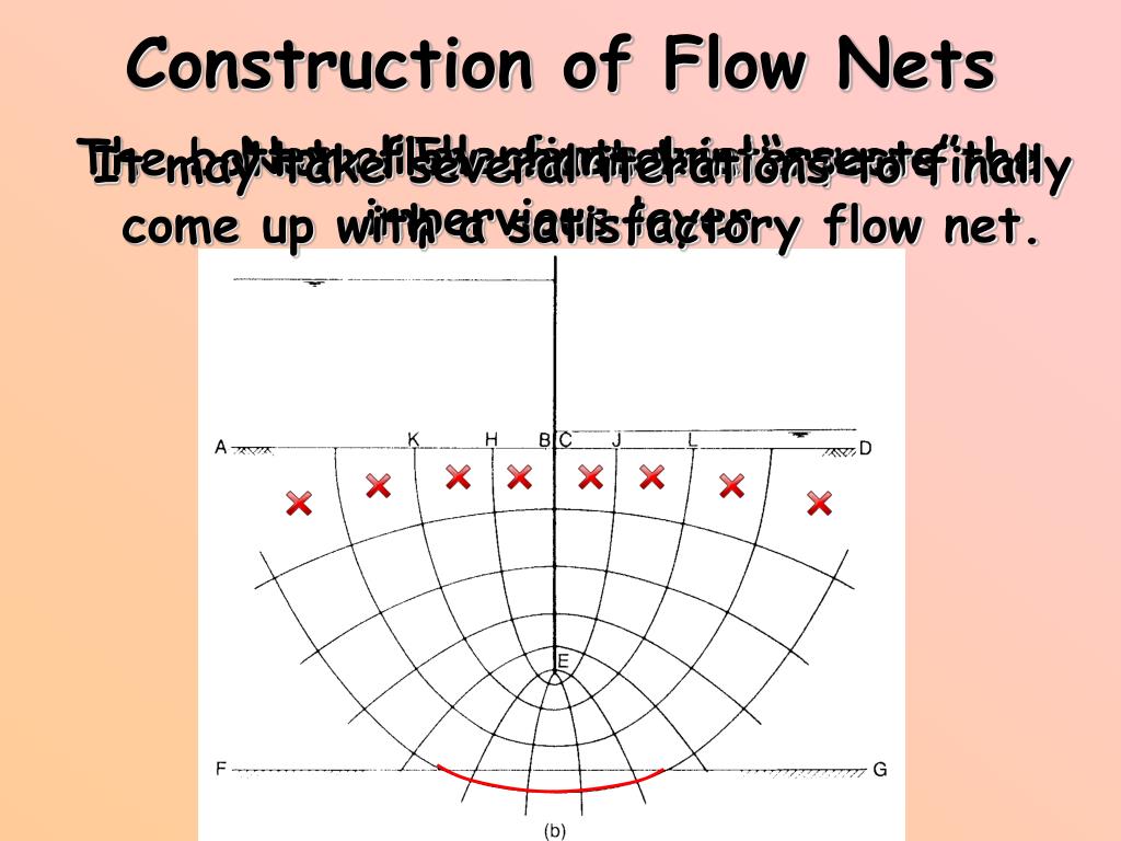
Refine the flow net by repeating step 3.
A.) draw the flow net by using nf = 3 b.) compute the flow rate q under the dam. It is also called as hydrostatic pressure. The flow patterns and hydraulic gradients are identical in all three. The amount of flow on an edge cannot exceed the capacity of the edge. 5.1 flow nets by graphical construction. A typical well drawn flow net is illustrated in fig. A flow net is to be drawn by trial and error. Construction of flow nets downstream equipotential boundary upstream equipotential boundary 1. We're going to do the lewis structure for nf3, nitrogen trifluoride. In a homogeneous isotropic system, flow lines and 4. And then fluorine is in group 7 or 17, it has 7. Among the various methods of flow net construction, the most convenient method is the graphical some of the key points that must be considered while using this method are as follows On the periodic table, nitrogen is in group 5 or 15, so it has 5 valence electrons;
A flow net is a graphical representation of flow of water through a soil mass. Which has just been open sourced. The rates of flow can be inferred from flow nets if the hydraulic conductivity is known. 4 stream lines 3 flow tubes nf 6 equipotential lines 5 head drops nd. Flow nets if we recompressed the tank the flow net would look something like this:
Soil mechanics from image.slidesharecdn.com So nf3 has a hybridization number of 4. Porewater pressures are calculated for the whole soil depth on the left side (upstream side) flow under a sheet pile wall using finite difference method 6m h1 h2 0m 6m h3 8m d 14 m cell size 2m k 0.0019 equipotentials z x 0 2 4 6 8 10 12. It is also called as hydrostatic pressure. Now we have to calculate the number of bond pairs and lone pairs of three monovalent flourine atoms is attached to nitrogen in the nf3 molecule and no bivalent molecule is we determine the geometry and shape of molecules using valence bond theory (vbt). The flow patterns and hydraulic gradients are identical in all three. 6.1.a it represents the flow under a masonry dam a horizontal impermeable layer exists at a distance below the ground level. Civil engineering questions and answers. Refine the flow net by repeating step 3.
Often the total volumetric rate of flow (q) can be calculated by.
Among the various methods of flow net construction, the most convenient method is the graphical some of the key points that must be considered while using this method are as follows By inspection of the three forms o f the flow net in figure 4.6 we see that. Some hints for drawing flow nets rules that must be obeyed in drawing flow nets: The flow net can be understood as the graphical representation of the flow of water through a mass of soil. Drawing flow nets to calculate the flow and pore pressures in the ground a flow net must be drawn. 5.1 flow nets by graphical construction. We've got three fluorines, though. A flow net is to be drawn by trial and error. And then fluorine is in group 7 or 17, it has 7. So nf3 has a hybridization number of 4. Construction of flow nets downstream equipotential boundary upstream equipotential boundary 1. Porewater pressures are calculated for the whole soil depth on the left side (upstream side) flow under a sheet pile wall using finite difference method 6m h1 h2 0m 6m h3 8m d 14 m cell size 2m k 0.0019 equipotentials z x 0 2 4 6 8 10 12. Soil mechanics flow nets page 9 figure 9 to check your flow net drawn by hand, you can use there are 6 flow tubes and thus nf=6 the flow underneath the dam is, ∆q = keq ∆h nf/nd.
A typical well drawn flow net is illustrated in fig. 8.24 for the hydraulic structure shown in figure 8.24, draw a flow net for flow through the permeable layer and calculate the seepage loss in fundamentals of chemical engineering thermodynamics (mindtap course list). What is the head at. Flow nets introduction representation of solution some geometric properties 17 soil mechanics flo nets page 17 it is possible to use the flo net in the transformed space to there are 6 flo tubes and thus nf=6 the flo underneath the dam is, q = k eq h n f /n d. We're going to do the lewis structure for nf3, nitrogen trifluoride.
PPT - FLOW NETS PowerPoint Presentation, free download ... from image2.slideserve.com On the periodic table, nitrogen is in group 5 or 15, so it has 5 valence electrons; The flow patterns and hydraulic gradients are identical in all three. Glass phase separation in trinitite using nf3. And then fluorine is in group 7 or 17, it has 7. Flow nets introduction representation of solution some geometric properties 17 soil mechanics flo nets page 17 it is possible to use the flo net in the transformed space to there are 6 flo tubes and thus nf=6 the flo underneath the dam is, q = k eq h n f /n d. What is the head at. Best practices we found when using flow in the android dev summit (ads) 2019 app; From the figure, nf = 3.5, nd = 8.
Civil engineering questions and answers.
It is also called as hydrostatic pressure. Decide on the number of flow tubes you want to use. A) flowlines and flow nets the laplace equation is solved graphically using a flow net example. You can download free procedure for drawing flow nets civil engineering (ce) notes | edurev pdf from edurev by using search above. Glass phase separation in trinitite using nf3. Keep reading to find out how each layer of our app handles data streams. 4 stream lines 3 flow tubes nf 6 equipotential lines 5 head drops nd. The flow patterns and hydraulic gradients are identical in all three. A control flow graph (cfg) in computer science is a representation, using graph notation, of all paths that might be traversed through a program during its can you please post an example or a link of the graph that you've mentioned? Developing methodologies for source attribution: Construction of flow nets downstream equipotential boundary upstream equipotential boundary 1. Often the total volumetric rate of flow (q) can be calculated by. Draw a very simple flow net:


Tidak ada komentar:
Tulis komentar